Titon HRV Home Assistant/HomeKit Automation
Overview
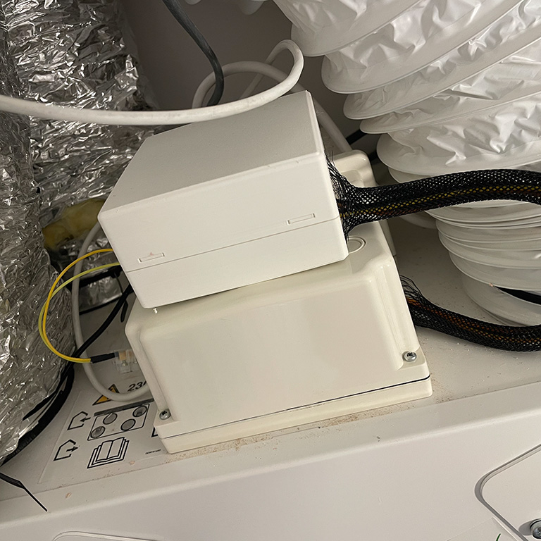
As with many new builds, our apartment came with a Heat Recovery Ventilation system, specifically a Titon HRV1.6 Q Plus. We found this could dry the air, and it would regularly drop to 30% relative humidity or below.
The unit comes with some limited controls on the front, allowing fan speed settings from 1 (slowest) through to 4 (highest). However, it will only stay at the new speed for about an hour before reverting to the default speed of 2. The main problem came from the “boost”, as both bathrooms and the kitchen have an on/off boost switch. If you forget to switch this off, the unit will stay in boost mode and can get even drier.
My initial plan was to monitor the switch’s state using an ESP32 or spare Pi GPIO pins and generate an alert to remind people to turn it off again. I checked out the manual for the HRV unit (page 24) to see what would be needed, eg voltages and wiring. While the specification is unclear on the voltage for that circuit, it did reveal the existence of a setback input that can be used to reduce ventilation without the timeout. This was not something that the builders had connected!
The switches are simple on/off, like light switches, meaning the Titon inputs can be easily controlled via relays, regardless of voltage. A quick search on Amazon found that ESP32 boards with mains-voltage relays already exist, likely far more than needed, and I ended up ordering a four-relay ESP32 board for a reasonable price. Two relay versions also exist, but were not readily available at the time I ordered.
Historically, I have written my own C code for ESP devices and output the MQTT myself. However, even if you have experience in writing embedded code, the HomeAssistant MQTT auto-discovery can be difficult to get right. So, for simplicity, I was keen to try ESPHome.
Flashing the board
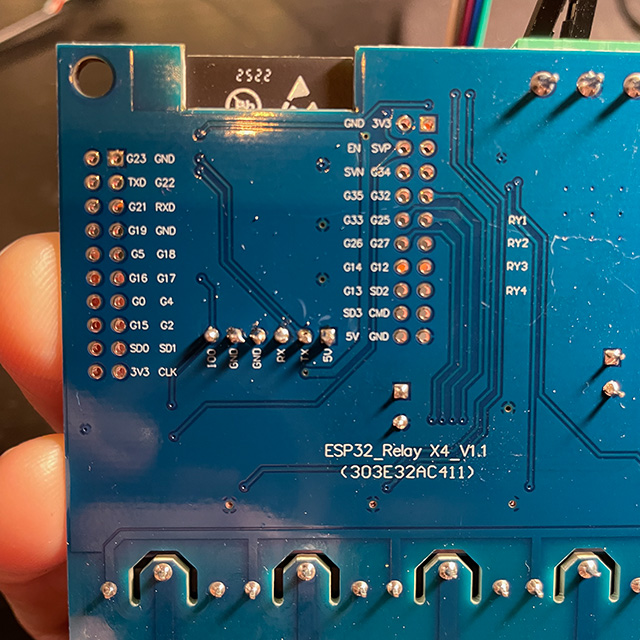
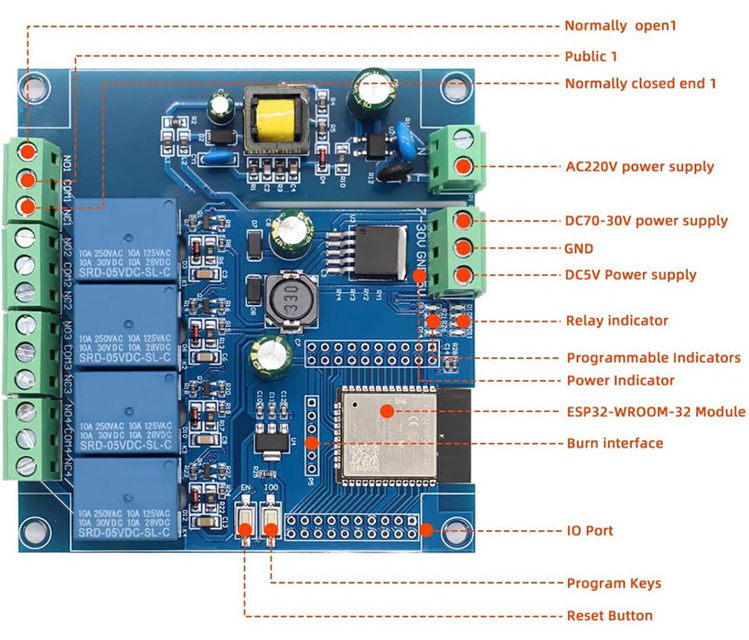
The board came with no documentation, but the Amazon page shows the basic layout and the pins are clearly labelled on the reverse. It was immediately obvious that GPIOs 32, 33, 25 and 26 were in use for relay control. In ESPHome, that looks like this:
  switch:
    - platform: gpio
      name: "Boost"
      id: boost
      pin: GPIO32
    - platform: gpio
      name: "Setback"
      id: setback
      pin: GPIO33
I also decided to use GPIO 18 as an input to monitor the state of the existing boost buttons and control the boost relay appropriately. This is controlled locally on the board via some very simple ESPHome scripting, so the boost switches will still work even if HomeAssistant is offline. It also allowed for a one-hour timeout if someone forgets to turn the boost off again after a shower.
    binary_sensor:
      - platform: gpio
        name: "Boost Switch"
        id: boost_switch
        filters:
          # Debounce the switch. (Why 2 seconds? Read on...)
          - delayed_on: 2s
        pin:
          number: GPIO18
          # Pulled up when off, when grounded via the switch this indicates "on"
          inverted: true
          mode:
            input: true
            pullup: true
        on_state_change:
          then:
            script.execute: do_boost

    script:
      - id: do_boost
        # If the switch is toggled off again, restart the script and any timers.
        mode: restart
        then:
          - if:
              condition:
                binary_sensor.is_on: boost_switch
              then:
                - switch.turn_off: setback
                - switch.turn_on: boost
                - delay: 60 min
                - switch.turn_off: boost
              else:
                - switch.turn_off: boost
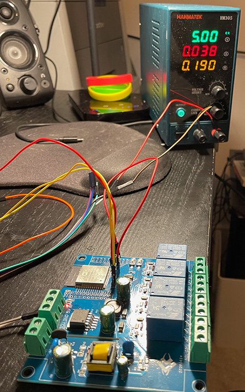
The only difficulty getting this working was during the initial flashing of the board, via a USB-to-serial adaptor that exposes the necessary pins. This is a one-off task, because subsequent re-flashing can be done over WiFi without needing to uninstall the board. Soldering one of the supplied headers onto the 6-pin re-flashing header is quick enough, and you don’t even need to use the IO0 pin on this header, as there is a convenient button on the board itself that you can hold down while booting.
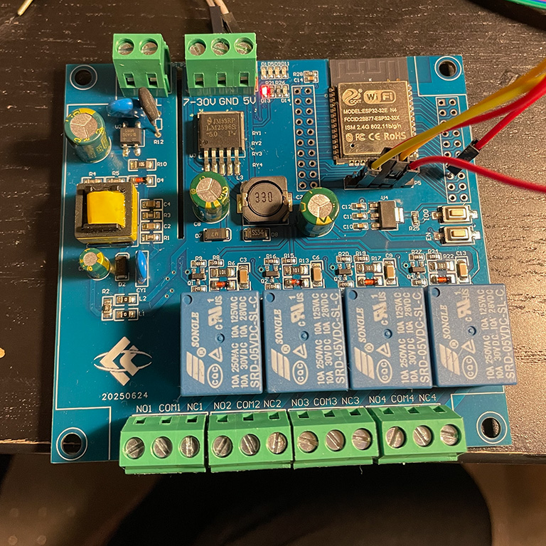
Unfortunately, no matter what I did, the board would not enter flash mode and was not responding to either esptool or ESPHome. It seems that, on this board, the GPIO2 pin somehow ends up set high. This is not a problem I had encountered before on ESP32 boards, because most boards do not use this pin themselves, and it is not connected unless the user does something with it. In this “floating” state, the ESP32 will enter boot mode. Fortunately, checking the relevant documentation revealed the issue, and grounding the pin during boot, the red wire in the image above, solved the problem.
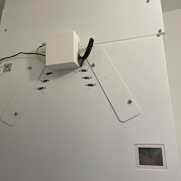
Installation
All that should remain is to 3D print an appropriate case, which I did using the case designer here, and install it. The ESP board does come with a mains power input, which I was hoping to use. Unfortunately, at least in our installation, the wiring is behind the metal enclosure with the inlet/outlet pipes in, and the WiFi signal was not strong enough to penetrate it. I was wary of extending the mains power supply outside the HRV unit, so instead attempted to connect the ESP32 board to the 12V power supply that also runs the display unit on the front of the HRV. (See page 23 of the manual)
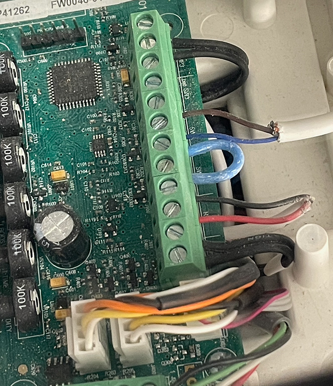
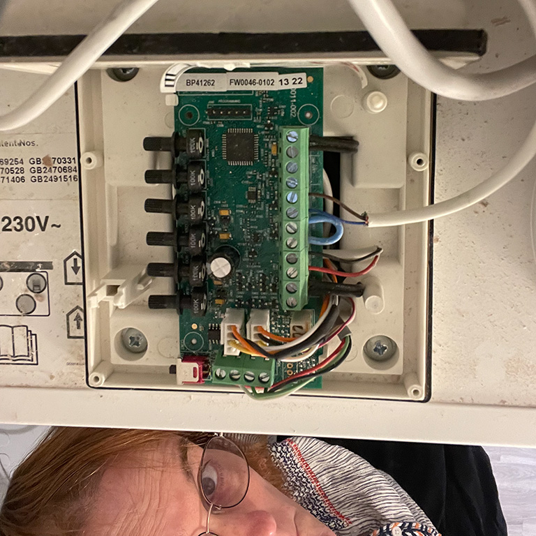
Wiring is straightforward, but do check the manual first; on my unit, only the cover for the front half of the electronics compartment should be removed. I did turn off the mains power to the unit whenever working on it, just in case, but the other half may contain mains voltages.
The very lightweight mains cable (Brown/Blue) in the photo is the original Boost Switch wiring, installed by the builders, and which I moved into a new terminal block. A couple of standard Dupont female-to-male jump wires went from there to GPIO18/ground on the new board, after soldering on another of the supplied headers. (The yellow wires in the photo are the jump wires, and you can slightly see the terminal block, as I forgot to include space in the case for mounting.)
Power from the Titon’s 12V supply initially went into the 7-30V input/GND, and the Titon’s Boost and Setback (SW2 and SW3) go into NO1/COM1 and NO2/COM2, respectively. (“Normally Open” and “Common”)
This was certainly not a manufacturer-recommended approach, but the new board pulls less than 200mW from a bench power supply. As a result, I was confident that this would be enough.
Unfortunately, that was not the case. The HRV unit, including the “auralite” control/display unit whose power I was scavenging, seemed quite happy. Despite that, the extra power required to close the relay caused the ESP32 to reboot. This may be due to insufficient power supply smoothing with a diode and capacitor on the input, but to get things running, the board is running off a separate 5V mains power supply for now.

Post-installation issues
Those paying attention will have noticed the 2s debounce configured on the Boost Switch input. A few minutes after installing the unit, I heard the relays turning on and off very rapidly. The HomeAssistant logs immediately revealed the problem: The Boost Switch input was toggling repeatedly between on and off.
Setting delayed_on: 2s stopped the relays from triggering continuously, but after a few more minutes, the input settled permanently into the “on” state. Completely removing power from the board and then powering it up again caused the issue to repeat: first, an accurate reading, followed by a period of rapid cycling and finally settling in the on state, i.e. the pin being pulled low more than the ESP32’s internal resistors could manage to pull it up high.
For now, I have disabled the boost switch input by commenting out the on_state_change section in the YAML configuration. Longer term, a suitable external pull-up resistor will be needed on GPIO18 to connect it to 3.3V, as I suspect the Boost Switch wiring does leak a little current.
Integration with HomeKit
Using HomeKit Bridge, it is fairly straightforward to integrate Home Assistant with HomeKit. However, it is necessary to filter the devices if you have already imported devices in the opposite direction, from Apple HomeKit into Home Assistant. This can be done via Home Assistant’s configuration.yaml:
homekit:
  - name: Home Assistant Bridge
    port: 21061
    filter:
      include_entities:
        - switch.titon_hrv_boost
        - switch.titon_hrv_setback
# Appears as an occupancy sensor in HomeKit
#        - binary_sensor.titon_hrv_boost_switch
This works well and also allows control of the setback/boost switches from the Home app and from Siri. Unfortunately, while getting the physical switch status into HomeKit this way is pretty painless, it ends up being displayed as an “occupancy sensor”, which is confusing and may break some automations: See this GitHub issue for a short discussion. I just disabled exporting the switch into HomeKit for now.
Full ESPHome YAML configuration
esphome:
  name: titon-hrv
  friendly_name: Titon HRV

esp32:
  board: esp32dev
  framework:
    type: esp-idf

logger:

api:
  encryption:
    key: ...

ota:
  - platform: esphome
    password: ...

wifi:
  ssid: !secret wifi_ssid
  password: !secret wifi_password

switch:
  - platform: gpio
    name: "Boost"
    id: boost
    pin: GPIO32
  - platform: gpio
    name: "Setback"
    id: setback
    pin: GPIO33
  - platform: gpio
    name: "Relay 3"
    pin: GPIO25
  - platform: gpio
    name: "Relay 4"
    pin: GPIO26

binary_sensor:
  - platform: gpio
    name: "Boost Switch"
    id: boost_switch
    filters:
      - delayed_on: 2s
    pin:
      number: GPIO18
      inverted: true
      mode:
        input: true
        pullup: true
    on_state_change:
      then:
        script.execute: do_boost

script:
  - id: do_boost
    mode: restart
    then:
      - if:
          condition:
            binary_sensor.is_on: boost_switch
          then:
            - switch.turn_off: setback
            - switch.turn_on: boost
            - delay: 60 min
            - switch.turn_off: boost
          else:
            - switch.turn_off: boost